
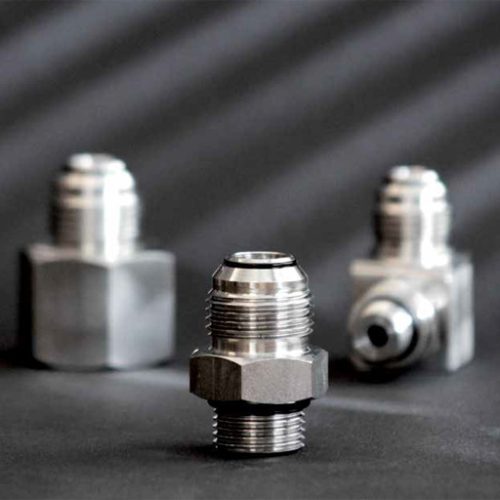
JIC FLARE FITTINGS
All GS-JIC 37° flare fittings comply with SAEJ 514 (ISO 8434-2). In addition to basic JIC 37° flare fittings, GS-Hydro also delivers special JIC 37° flare fittings – either with or without an O-ring – which are type approved by Det Norske Veritas. GS-Hydro’s JIC-fittings are specified by NORSOK (specification classes FS70, IS70) to be used offshore.
Technical Data
| Carbon steel | AISI 316 | AISI 316 and Carbon steel with o-ring | |||
| Tube OD, mm |
Tube OD, inch |
Max. tube wall thickness, mm |
Max. allowable working pressure, bar |
Max. allowable working pressure, bar |
Max. allowable working pressure, bar |
| 6 | ¼ | 1.5 | 430 | 430 | 600 |
| 8 | 5/16 | 1.5 | 430 | 430 | 600 |
| 10 | 3/8 | 1.5 | 430 | 430 | 600 |
| 12 | ½ | 2.0 | 350 | 350 | 490 |
| 16 | 5/8 | 2.5 | 350 | 350 | 490 |
| 18 | ¾ | 2.5 | 350 | 350 | 490 |
| 20 | – | 2.5 | 350 | 350 | 490 |
| 22 | 7/8 | 2.5 | 350 | 350 | 490 |
| 25 | 1 | 3.0 | 250 | 250 | 420 |
| 30 | – | 4.0 | 250 | 250 | 420 |
| 38 | 1½ | 5.0 | 250 | 250 | 420 |
Note! All pressures are for fittings and NOT for tubes |
|||||
Carbon steel and stainless steel (AISI 316) GS-JIC 37° flare fittings without an O-ring may (according to the type approval from DNV) be used for the following media:
- Freshwater
- Seawater
- Sanitary
- Compressed air
- Hydraulic
- Fuel oil (JIC to NPTF only)
- Lubricating oil (JIC to NPTF only)
- Steam and condensate
- Fire water
- Deluge systems
Carbon steel and stainless steel (AISI 316) GS-JIC 37° flare fittings with an O-ring may be used (according to the type approval from DNV) for the following media:
- Freshwater
- Seawater
- Sanitary
- Compressed air
- Hydraulic
- Steam and condensate
- Nitrogen
- Shield gas
- CO2
- Fire water
The following O-ring materials should be used:
- For gas-media AFLAS 100H/100S
- For other media Nitrile 70 shore
Carbon steel and stainless steel (AISI 316) JIC 37° flare fittings may be used for a wide range of applications including hydraulic, freshwater, fuel and lubricating oil among others. The maximum allowable working pressure of JIC 37° flare fittings (according to ISO 8434-2) are as follows:
JIC 37° Flare Fittings (According to ISO 8343-2) |
|||
| Tube OD, mm |
Tube OD, inch |
Max. tube wall thk, mm |
Max. allowable working pressure, bar |
| 6 | ¼ | 1.5 | 350 |
| 8 | 5/16 | 1.5 | 350 |
| 10 | 3/8 | 1.5 | 250 |
| 12 | ½ | 2.0 | 250 |
| 16 | 5/8 | 2.5 | 250 |
| 20 | – | 2.5 | 200 |
| 22 | 7/8 | 2.5 | 160 |
| 25 | 1 | 3,0 | 160 |
| 30 | – | 3,0 | 125 |
| 32 | 1 1/4 | 3,0 | 125 |
| 38 | 1 1/2 | 3,0 | 100 |
Kategorie: JIC Flare Fittings
 English
  简体中文
简体中文